Greetings to everyone on this fourm and to everyone around the world wherever you are for this is my first posting. And Happy New Year everybody!
First off, I'm probably one of the minority on this one, but I'm very interested in building the Sola Sound Tonebender Mark 1.5. Now I read the history about the Sola Sound Tonebenders on D*A*M stompboxes. According to that webpage, the MK 1.5 was very similar to the Fuzz Face except that it used Mullard OC75 Germanium Transistors. The Fuzz Face used NKT275 or the AC128 Germanium Transistors.
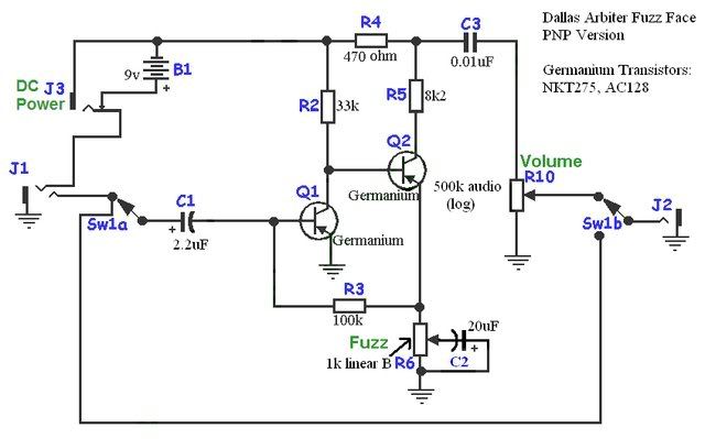
Just recently, I purchased the Fuzz Face PCB from General Guitar Gadgets. Here is the layout for the Fuzz Face.
http://www.generalguitargadgets.com/pdf ... lo_pnp.pdf
Resistor 1, Diode 3, and Capacitors 4 & 6 are optional.
What changes do I have to make in order to make the Fuzz Face sound like the 1.5.....or do I just throw in the OC75 Transistors and be done with it?
David
The Sola Sound Tonebender MK 1.5. Help!
Moderator: The Captain
-
Analogman78
- Posts: 7
- Joined: Wed Dec 31, 2008 8:51 am
- Location: Warren, Michigan, USA (Detroit suburb)
-
tatter

- Posts: 643
- Joined: Thu Aug 28, 2008 12:22 pm
- Location: Blackpool, England
Re: The Sola Sound Tonebender MK 1.5. Help!
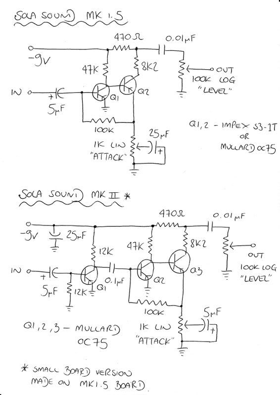
Here's Dave's MK1.5 from the old forum, you should be able to compare this with a fuzz face schematic and find the different parts
You'll need to make sure your PCB is for positive ground (PNP) transistors as well
You'll need to make sure your PCB is for positive ground (PNP) transistors as well
http://www.myspace.com/sinisterfootwear
http://www.reverbnation.com/sinisterfootwear
Fender Vintage Player Stratocaster > D*A*M AA > Arion SAD-1 > Line 6 M9 > Ibanez 850 Mini Fuzz > CAE Boost / Line Driver
http://www.reverbnation.com/sinisterfootwear
Fender Vintage Player Stratocaster > D*A*M AA > Arion SAD-1 > Line 6 M9 > Ibanez 850 Mini Fuzz > CAE Boost / Line Driver
-
Analogman78
- Posts: 7
- Joined: Wed Dec 31, 2008 8:51 am
- Location: Warren, Michigan, USA (Detroit suburb)
Re: The Sola Sound Tonebender MK 1.5. Help!
Tatter, you are awesome! Thank you for the schematic!tatter wrote:You'll need to make sure your PCB is for positive ground (PNP) transistors as well
The PCB that I bought from General Guitar Gadgets can be wired for either PNP or NPN Transistors.
Wow! The Tonebender MK 1.5 is almost exactly like fuzz face except that you change two capacitors, one resistor, and the potentiometer....and of course the transistors. I already can't wait to have this built! Again Tatter, thank you again.
David
-
tatter
- Posts: 643
- Joined: Thu Aug 28, 2008 12:22 pm
- Location: Blackpool, England
Re: The Sola Sound Tonebender MK 1.5. Help!
No problem, it's David Main's schematic i just put the link to it. He's a lovely fella that Dave!
http://www.myspace.com/sinisterfootwear
http://www.reverbnation.com/sinisterfootwear
Fender Vintage Player Stratocaster > D*A*M AA > Arion SAD-1 > Line 6 M9 > Ibanez 850 Mini Fuzz > CAE Boost / Line Driver
http://www.reverbnation.com/sinisterfootwear
Fender Vintage Player Stratocaster > D*A*M AA > Arion SAD-1 > Line 6 M9 > Ibanez 850 Mini Fuzz > CAE Boost / Line Driver
-
Analogman78
- Posts: 7
- Joined: Wed Dec 31, 2008 8:51 am
- Location: Warren, Michigan, USA (Detroit suburb)
Re: The Sola Sound Tonebender MK 1.5. Help!
Okay, a little bit of a problem with the capacitors. Now I know that it calls for a 5uF capacitor (between the "In" and the Q1 tracing) and a 25uF capacitor (right at the 1k attack potentiometer). Maybe it's me (but I could be wrong) but it seems like the 5uF and the 25uF capacitors seem to be hard to come by.
The closest value to a 5uF would be a 4.7uF, higher would be 6.8uF.
The closest to the 25uF would be a 22uF (but in this case, the 22uF would be set back to Fuzz Face specs), the highest would be 33uF.
If I can't find the required capacitors, can I substitute the 5uF and the 25uF capacitors with the ones closest? And if it is yes, which values caps should I go with?
David
-
fuzzer
- Posts: 104
- Joined: Tue Nov 18, 2008 5:19 pm
Re: The Sola Sound Tonebender MK 1.5. Help!
The 25[uF] is just a filter cap on the second circuit, so its value is not very critical; I think you can get away with using 4.7[uF] for the 5 [uF], and if you need to have the value, then parallel a 4.7[uF] with a 0.33[uF] cap.
The 5 [uF] and 25 [uF] (that are used on the pots labeled 'Attack') are bypass capacitors, they also condition the bass response of the circuit, the bigger the cap, more bass you get (more gain for the lower frequencies). Make yout mind from there.
I hope that helps.
The 5 [uF] and 25 [uF] (that are used on the pots labeled 'Attack') are bypass capacitors, they also condition the bass response of the circuit, the bigger the cap, more bass you get (more gain for the lower frequencies). Make yout mind from there.
I hope that helps.
-
Analogman78
- Posts: 7
- Joined: Wed Dec 31, 2008 8:51 am
- Location: Warren, Michigan, USA (Detroit suburb)
Re: The Sola Sound Tonebender MK 1.5. Help!
Since you guys gave me the help and info on the Tonebender MK 1.5, I want to share to everyone on how to turn your Fuzz Face pedal or clone pedals into the Tonebender MK 1.5.
First, here's the Dallas Arbiter Fuzz Face schematic.
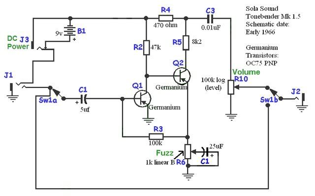
Second is the Tonebender MK 1.5 schematic.
Now, here's the Tonebender MK 1.5 schematic again, only this time the ones that are circled are the ones that you change on the Fuzz Face PCB.
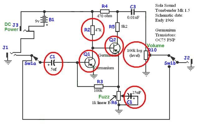
NOTE: THE DC POWER JACKS WERE NOT IN THE ORIGINAL SCHEMATICS
If you have a Reissue Fuzz Face, a BYOC Ultimate Fuzz/E.S.V. Fuzz or the General Guitar Gadgets Fuzz Face, these are the following modifications that will change your Fuzz Face into a MK 1.5:
3 CAPACITORS
1. 2.2uF Aluminim Electrolytic: Change to 5uF. If you cannot find a 5uF Capacitor, you can use a 4.7uF or a 6.8uf Capacitor. If you want the exact value, parallel a 4.7uF with a 0.33uF cap.
2. 20uF Aluminim Electrolytic (currently, the kits use 22uf): Change to a 25uF Capacitor. If you cannot find a 25uF, use a 33uF cap. If you want the exact value, parallel a 10uf with a 15uf cap.
3. 0.1uF Film (on the Build Your Own Clone PCB's): Change to 0.01uF (no changes on the General Guitar Gadgets PCB for this capacitor).
1 (or 2) RESISTORS:
1. 33k: Change to a 47k resistor.
2. 1k on the GGG Fuzz Face PCB: Change to 8k2 resistor. This change is optional. If you want to change it, you can. I'm not too sure if there's a difference, but I could be wrong. The 8k2 resistor was used on the Tonebender MK 1.5 & the Dallas Arbiter Fuzz Face.
POTENTIOMETER:
A500K Audio Volume Pot: Replace with A100k log
TRANSISTORS:
OC75 PNP Transistors.
For the General Guitar Gadgets Fuzz Face PCB, it'll take them no problem.
For the Build Your Own Clone Ultimate Fuzz PCB or the E.S.V. Fuzz PCB, you would have to switch the polarity of the circuit because it's set up for NPN Transistors. However, you can use the NPN equivalancy of the OC75 Transistors (like NTE103A Transistors for example) or OC139, OC140 and OC141 Transistors for they are NPN.
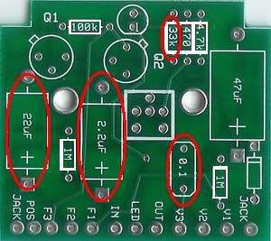
The Build Your Own Clone "Ultimate Fuzz" PCB. The ones circled in red are the ones that get modified.
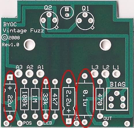
The Build Your Own Clone "E.S.V. Fuzz" PCB (Extra Special Vintage). Again, the ones circled in red are the ones that get modified.
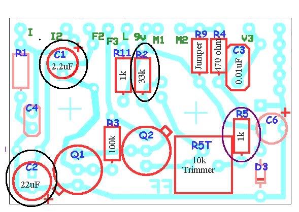
The General Guitar Gadgets "Fuzz Face" PCB. THe ones circled in Black are the ones that get modified. The R5 resistor circled Dark Purple is optional.
I want to thank Tatter for posting the Tonebender MK 1.5 Schematic, and for Fuzzer on sending me the message about the Capacitor values. Big thank you to both!
David
First, here's the Dallas Arbiter Fuzz Face schematic.
Second is the Tonebender MK 1.5 schematic.
Now, here's the Tonebender MK 1.5 schematic again, only this time the ones that are circled are the ones that you change on the Fuzz Face PCB.
NOTE: THE DC POWER JACKS WERE NOT IN THE ORIGINAL SCHEMATICS
If you have a Reissue Fuzz Face, a BYOC Ultimate Fuzz/E.S.V. Fuzz or the General Guitar Gadgets Fuzz Face, these are the following modifications that will change your Fuzz Face into a MK 1.5:
3 CAPACITORS
1. 2.2uF Aluminim Electrolytic: Change to 5uF. If you cannot find a 5uF Capacitor, you can use a 4.7uF or a 6.8uf Capacitor. If you want the exact value, parallel a 4.7uF with a 0.33uF cap.
2. 20uF Aluminim Electrolytic (currently, the kits use 22uf): Change to a 25uF Capacitor. If you cannot find a 25uF, use a 33uF cap. If you want the exact value, parallel a 10uf with a 15uf cap.
3. 0.1uF Film (on the Build Your Own Clone PCB's): Change to 0.01uF (no changes on the General Guitar Gadgets PCB for this capacitor).
1 (or 2) RESISTORS:
1. 33k: Change to a 47k resistor.
2. 1k on the GGG Fuzz Face PCB: Change to 8k2 resistor. This change is optional. If you want to change it, you can. I'm not too sure if there's a difference, but I could be wrong. The 8k2 resistor was used on the Tonebender MK 1.5 & the Dallas Arbiter Fuzz Face.
POTENTIOMETER:
A500K Audio Volume Pot: Replace with A100k log
TRANSISTORS:
OC75 PNP Transistors.
For the General Guitar Gadgets Fuzz Face PCB, it'll take them no problem.
For the Build Your Own Clone Ultimate Fuzz PCB or the E.S.V. Fuzz PCB, you would have to switch the polarity of the circuit because it's set up for NPN Transistors. However, you can use the NPN equivalancy of the OC75 Transistors (like NTE103A Transistors for example) or OC139, OC140 and OC141 Transistors for they are NPN.
The Build Your Own Clone "Ultimate Fuzz" PCB. The ones circled in red are the ones that get modified.
The Build Your Own Clone "E.S.V. Fuzz" PCB (Extra Special Vintage). Again, the ones circled in red are the ones that get modified.
The General Guitar Gadgets "Fuzz Face" PCB. THe ones circled in Black are the ones that get modified. The R5 resistor circled Dark Purple is optional.
I want to thank Tatter for posting the Tonebender MK 1.5 Schematic, and for Fuzzer on sending me the message about the Capacitor values. Big thank you to both!
David
Last edited by Analogman78 on Mon Feb 23, 2009 2:29 am, edited 3 times in total.
-
kennsol
- Posts: 3
- Joined: Fri Aug 29, 2008 8:15 pm
Re: The Sola Sound Tonebender MK 1.5. Help!
Can anybody please describe the sound of this unit? I tend to get this weird octave down- / semi out of tune-like effect when backing off the guitar volume. Cool as Hell! But is this normal with this circuit? I use AC125 with gains around 120.
Kenneth
Kenneth
-
playon

- Posts: 145
- Joined: Wed Nov 12, 2008 4:36 am
Re: The Sola Sound Tonebender MK 1.5. Help!
I much prefer this circuit with a smaller input cap, like a .1 metal film - it's not necessary that this cap be polarized and I think metal film ones sound better. With a smaller cap It's brighter and clearer, less tubby low end, (unless that's what you're after & you want to make an exact copy). I also found that it biased up nicely with the 8K2 cap if you have the right transistors, but if you want a trimpot a 20 or 25k seems to work better than the 10k.
This would be more like the Vox Tonebender, or the DAM 1966. This circuit and layout are posted on the Fuzz Central site:
http://fuzzcentral.ssguitar.com/voxbend ... ematic.gif
http://fuzzcentral.ssguitar.com/voxbend ... layout.gif
This would be more like the Vox Tonebender, or the DAM 1966. This circuit and layout are posted on the Fuzz Central site:
http://fuzzcentral.ssguitar.com/voxbend ... ematic.gif
http://fuzzcentral.ssguitar.com/voxbend ... layout.gif
"That's a nice little global economy you've got there -- it'd be a real shame if something happened to it..."
-
kennsol
- Posts: 3
- Joined: Fri Aug 29, 2008 8:15 pm
Re: The Sola Sound Tonebender MK 1.5. Help!
I use an 8k2 resistor on the collector of Q2 and find that this circuit seem to bias naturally with around -0,3V on the collector of Q1 and -7V on the collector of Q2. I immagine this to be pretty close to 'design values', or? This is with approximately 100 uA leakage in Q1 and gains of approx 110 - 120. I have found that higher leakage in Q1 tend to pull the collector of Q2 more negative. Besides: the weird octave like effect disappeared after some transistor swapping. Now there is only a hint left of octave up and the fuzz sound is great.
Who is online
Users browsing this forum: No registered users and 1 guest