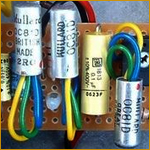
Right so Diodes are marked either 2483 or 12483 with a voltage drop of 0.53 V.
The Transistors are PNP Germanium and the one I measured has hFE of 192 (DCA55 used for testing). Pinout is the usual base in the middle and tag for emitter.
That resistor R5 is defo 27K with the violet band.
It is powered by 9V battery.
I'll get back to checking your wiring after work.
Garrett Fuzz Unit
Moderator: The Captain
-
moose

- Posts: 619
- Joined: Tue Jun 09, 2009 10:03 pm
- Location: Dublin
-
AmplifiedPartsTom
- Posts: 5
- Joined: Sun Oct 30, 2022 11:23 pm
Re: Garrett Fuzz Unit
Hi all, apologies for the delay - I ended up just wiring this circuit up in a mini pedal build which unsurprisingly took longer. I have one on the breadboard too for some tweaking. It sounds pretty sweet to me. The controls are pretty limited, as the "Attack" control is really just an output attenuator on the fuzz section. The clean section that runs in parallel makes the output particularly strange when engaged. The clean section is quite a bit quieter than the fuzz output, so mixing them is not very intuitive. With the clean section (volume control) turned all the way up and the fuzz turned all the way up, you do get a little more thickness to the signal than you would with no clean signal. I feel like it's maybe adding some of the low end back in. Although another strange thing is that the output of the clean section is inverted when it gets mixed back in with the fuzz, so it may be an odd effect of some frequency cancellation. I've mostly been using it with volume turned all the way down and fuzz all the way up.
I've tried out a few different clipping diode types. I went with 1N4001s in the final build. The output of this pedal is pretty darn quiet. There's no amplifying stage after the clipping diodes, so their Vfwd determines the max peak-to-peak voltage, and a lot of signal is dropped at the mixing stage which comes after the clipping diodes. Because the forward voltage of the diodes is going to have a direct effect on the output level, putting aside any different tonal characteristics, something with a large forward voltage is desirable here just for a more reasonable output volume. Fortunately, I actually thought the 1N4001s sounded best of the ones I tried, and those have a higher Vfwd than germaniums or the 0.53 moose measured. The output is just totally wimpy with germaniums. I had some old diodes with a Vfwd of 0.58, which is in the ballpark of the originals. Those sounded good, but I preferred the 1N4001s just a bit. I did not try anything with a higher forward voltage, but I'd be curious to know how a couple of series diodes or LEDs sound. I will try that very soon.
I did try removing the diodes entirely. It will give you a large output boost, and a different characteristic fuzz sound, but it sounds nice that way too. Stock, I think it's a really nice fuzz, barring the odd controls. Seems like the right amount of low-end gets removed to give a good cutting sound, and there's a good amount of high frequency content without being too harsh or piercing. It's a pretty squished/compressed sound. Leans a little bit more towards really squared off, 8-bit sounding fuzzes. It's not entirely there, but somewhere in-between that kind of sound and a more classic fuzz. With the diodes removed, the fuzz sound is more natural and less squished to my ears. It sounds solid that way too. Enough output gets dropped at the mixing stage that it's not deafening, but it's quite a bit louder with them removed.
I used 3x General Electric 2N1304 transistors (I went with an NPN build). The 2N1304s on the breadboard are 78 and 81 hfe in the fuzz section, 108 hfe in the boost. The 2N1304s in the pedal build are all 115-118 hfe. Leakage was very low, between 28 and 39 uA on all of them. I'd maybe say I slightly prefer the higher gain ones in the pedal, but the difference is pretty minor. The collectors of all 6 transistors (3 in each build) bias up to right around 6.0V. The transistor specs aren't far apart, but I think the base voltage divider probably helps get a consistent bias on these. I am curious to try out some other transistors with more leakage and a wider gain range to see if that's still true.
I added a "soften" pot to the pedal build (mostly because the enclosure had already been drilled for 3 pots), which is just a variable resistor in series with the diodes - attempting to allow myself to sort of blend between the sound with clipping diodes and the sound without. Results are somewhat mixed, there's a bit of tonal variety but I think a simple diode lift switch would be about as effective.
I'll want to play around with this circuit a bit, at least adding a gain control somewhere and trying to get a better output level. I'll post any interesting discoveries here. I was flying by the seat of my pants on the layout here so I don't have any kind of drawing, but if I make a turret board or stripboard layout I'll follow up.
- anglesm.png (739.27 KiB) Viewed 424 times
- sizesm.png (766.71 KiB) Viewed 424 times
- gutssm.png (841.44 KiB) Viewed 424 times
-
Zuff-1A

- Posts: 1271
- Joined: Wed Oct 26, 2011 2:55 pm
- Location: Estonia, Tallinn
-
moose
- Posts: 619
- Joined: Tue Jun 09, 2009 10:03 pm
- Location: Dublin
Re: Garrett Fuzz Unit
I'm gonna have to build one now too and try match the sounds of the original unit. I'll keep in touch.
Who is online
Users browsing this forum: No registered users and 1 guest